Frequency Combs
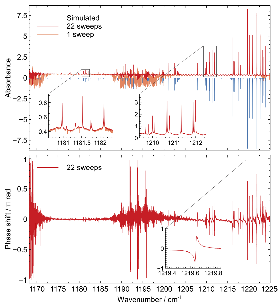
Quantum cascade laser (QCL) frequency combs allow for broadband and fast spectral acquisitions in the mid-IR range, with typical acquisition speeds of μs for dual-comb spectroscopy (see external page IRsweep), with a compact, power-efficient system without moving parts. In addition to the intensity (absorption) spectrum, the coherence properties of the frequency combs allow for the retrieval of phase information, whereby both the real and imaginary part of the refractive index can be deduced [1].
The ultimate limit for spectroscopy in a given wavelength range, is set by the signal-to-noise ratio on the detector after the sample has been interrogated. Therefore, it is of utmost importance to minimize the noise from the QCL itself (in addition to environmental factors and the current source). Even if all other noise sources could be eliminated, quantum physics dictates that there is still some residual quantum noise originating from spontaneous emission (the so-called Schawlow-Townes limits) as well as from the current-carrying electrons (shot noise). QCL frequency combs can be stabilized by injecting a very stable signal at a frequency \( f_{rep} \) equal to the inverse round-trip time of the laser, which lies in the radio frequency (RF) domain. The injection may lock the frequency difference of the comb lines \( f_{rep} \) to this repetition frequency if the injected frequency is close enough.
As mentioned before, the noise of the QCL comb is eventually limited by quantum fluctuations. Heisenberg’s uncertainty relation dictates that the product of the uncertainty in two “conjugate” variables always have to be larger than some fixed value. Thus, if one is willing (and able) to trade low noise in one measurement variable, for increased noise in its conjugate variable, it is possible to reduce the noise in the first variable below the shot noise limit. Such variables exist for the laser field, for example the phase and amplitude of a monochromatic laser beam; by increasing the phase noise, the amplitude noise can be “squeezed”. Such states are non-classical, and called “squeezed” states of light, and are routinely generated in quantum optics laboratories by shining light through nonlinear crystals with large optical nonlinear coefficients. It is also possible to generate squeezing between different teeth of the comb, so-called two-mode or multi-mode squeezing, and has been demonstrated in micro-resonator combs[2].
Curiously, the QCL also has the key ingredient necessary for squeezing light; a strong third (and second) order nonlinear coefficient, which is responsible for the generation of frequency combs (as demonstrated by the frequency comb formation in a ring cavity QCL [3]). Within the Qombs project, we are committed to finding and optimizing the generation of such quantum states of light in QCLs, by performing simulations and optimization of the active regions and development of a theoretical framework for squeezing in the QCL (and similar) system.
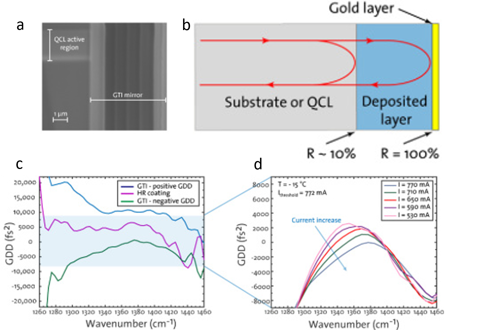
In conventional QCLs, the dispersion is too large to generate stable QCL combs in a large part of the dynamical range of the lasers. It is therefore of major interest to compensate this dispersion and get better comb performance. We have developed a dispersion compensation scheme based on a Gires–Tournois interferometer (GTI) directly integrated into the QCL-comb improves the comb performance [4]. The GTI usually consists of many layers of dielectric materials (e.g., Al2O3 and SiO2) and terminates with a gold layer. Figure 3(a) shows a cross section of a QCL-comb coated with a GTI mirror taken with a scanning electron microscope. In the GTI mirror, dispersion is introduced as the phase of the reflected light becomes frequency dependent due to the resonance effect introduced by the optical cavity as shown in Fig. 3(b). The dispersion is periodic with a period dependent on the length and on the refractive index of the material. By careful control of these parameters, a GTI mirror can introduce positive or negative dispersion to the QCL-comb. The Group delay dispersion (GDD) of devices with different coatings is shown in Fig. 3(c). The QCL-comb coated with a standard HR coating is operating with a total positive GDD of 4131fs2 (measured at 1330cm−1). A similar device coated with a GTI mirror introducing positive GDD shows a total dispersion of 10602 fs2. In contrast, the device coated with a GTI mirror designed to introduce negative dispersion is operating with a total negative GDD of −3546 fs2. Figure 3(d) shows the GDD of the device coated with a GTI mirror introducing negative dispersion for different driving currents.
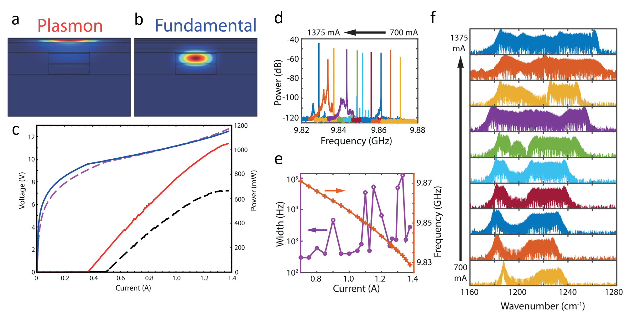
The dispersion compensation in mid-infrared quantum cascade laser frequency combs can also be realized by using the coupling of a dielectric waveguide to a plasmonic resonance in the highly doped top cladding layer [5]. In such a plasmon-enhanced waveguide, the active region is sandwiched between a low doped InP bottom and top claddings. In the last layer of the top cladding, the doping is increased in order to shift the plasma frequency close to the laser frequency. The strong decrease of the refractive index in this layer has the effect of increasing the confinement of the fundamental mode and decreasing the optical losses associated with the metallic top contact of the device. The profile of the fundamental mode (at the lasing frequency of 1250cm-1) and plasmon mode (at the frequency of 700cm−1) were shown in Fig. 4(a) and 4 (b), respectively. Figure 4 (c) shows the light-current-voltage (LIV) characteristics of a QCL comb device based on a plasmon-enhanced waveguide [6]. Optical output power more than 1W was achieved. In this device, different beatnote types were recorded across the dynamical range and are shown in Fig. 4(d). For most currents, a sharp beatnote was observed. The beatnote width at –20 dB and the beatnote frequency as a function of current are shown in Fig. 4(e). The corresponding optical spectra measured using a Deuterated triglycine sulfate detector are shown in Fig. 4 (f). A continuous bandwidth of 82cm-1 has a power per mode above 1 mW with an average power of 4.1mW was achived.
Fig. 4. (a) and (b) 2D profiles of the plasmon and fundamental modes. (c) LIV characteristics of a 4.5 mm long laser based on plasmon-enhanced waveguide. (d) Beatnotes measured at different driving currents. (e) Beatnote linewidth at -20 dB and frequency for the different currents. (f) Corresponding optical spectra.
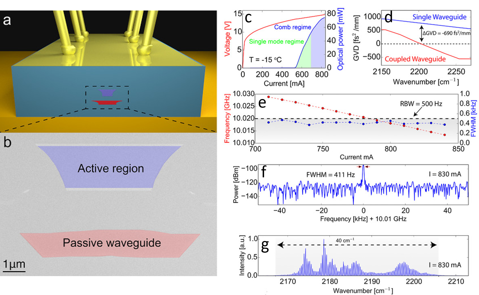
This plasmon-enhanced waveguide cannot be applied to shorter wavelengths due to the difficulty to scale the plasma frequency accordingly and the introduction of unavoidable free carrier losses. We demonstrated that coupling the optical mode inside a passive dielectric waveguide engineered in the device top cladding to realize dispersion compensation in shortwave QCL [7]. As shown in Fig. 5(a), the device integrates a passive InGaAs waveguide close to the active region. A scanning electron micrograph (SEM) image of the device front facet is displayed in Fig. 5(b). The LIV of a 4.6μm wavelength QCL is shown in Fig. 5(c). The threshold current is 530mA and the output power reached 75mW at rollover. The GVD of QCL with and without (reference device) the additional passive waveguide are shown and compared in Fig. 5 (d). For the reference device, a GVD as large as 740fs2.mm−1 is deduced at 2200cm−1, while for the device including the passive waveguide a GVD of only 50 fs2.mm−1 is deduced at 2200cm−1. This confirms that the coupling to the passive waveguide reduced the dispersion of the device (ΔGVD = −690 fs2.mm−1). For the coupled waveguide device, narrow beatnotes with full width at half maximum (FWHM) less than 500Hz were measured on the whole multi‐mode dynamical range as shown in Fig. 5(e). At a current of 830mA the intermode beatnote has a FWHM ≃ 411Hz (Fig.3 (f)) and the optical spectrum spans 40cm−1 (Fig. 3(g)).
Fig. 5 (a) Schematic view of a QCL with a coupled-waveguide. (b) SEM picture of the fabricated device. (c) LIV of the device measured at −15°C in continuous wave. (d) GVD of QCLs with and without the additional passive waveguide. (e) Intermode beatnote frequency (blue) and FWHM (red) as a function of current. (f) Intermode beatnote measured at −15°C for a current of 830mA. (g) Optical spectrum measured in continuous wave at −15 °C for a current of 830mA.
References
[1] M. Gianella et al., “High-resolution and gapless dual comb spectroscopy with current-tuned quantum cascade lasers,” Opt. Express, vol. 28, no. 5, p. 6197, Mar. 2020, external page doi
[2] S. Gerke et al., “Full Multipartite Entanglement of Frequency-Comb Gaussian States,” Phys. Rev. Lett., vol. 114, no. 5, p. 050501, Feb. 2015, external page doi
[3] B. Meng et al., “Mid-infrared frequency comb from a ring quantum cascade laser,” Optica, vol. 7, no. 2, pp. 162–167, Feb. 2020, external page doi
[4] G. Villares, et al., “Dispersion engineering of quantum cascade laser frequency combs,” Optica, vol.3, no.3, pp. 252–258, Mar. 2016, external page doi
[5] Y. Bidaux et al., “Plasmon-enhanced waveguide for dispersion compensation in mid-infrared quantum cascade laser frequency combs,” Opt. Lett., vol. 42, no. 8, pp. 1604–1607 Apr. 2017, external page doi
[6] P. Jouy, et al., “Dual comb operation of 8.2um quantum cascade laser frequency comb with 1W optical power,” Appl. Phys. Lett., vol. 111, no. 14, p.141102, Oct. 2017, external page doi
[7] Y. Bidaux et al., “Coupled-Waveguides for Dispersion Compensation in Semiconductor Lasers,” Laser Photon. Rev., vol. 12, no. 5, p. 170032, Mar. 2018, external page doi


