Magneto-transport controlled by Landau polariton states
In systems with strong light matter coupling, hybrid excitations, called polaritons, arise. We recently investigated the role of the electronic component of polaritons in the magneto-transport of a coupled light-matter system, showing that the coupling to a Terahertz (THz) resonator modifies the linear direct current resistivity [1]. We also studied the different contribution to the coupled system of localized and delocalized states, by looking at the magneto-transport under weak illumination.
Polaritons are usually investigated by accessing the optical component of the coupled system. We developed a platform, which allows us to access directly the electronic part. Performing magneto-transport measurements with and without external illumination, we can probe the electrons at the Fermi levels, which are, at the same time, contributing to the transport and to the polariton state.
In Fig.1, we show a schematic representation of the sample. The substrate consists of a GaAs/AlGaAs quantum well. The quantum well is shaped into a Hall bar geometry, where contacts are defined, enabling the measurement of transverse and longitudinal resistivities. An a.c. current (I = 100 nA) is applied in the x direction along a 40-μm-wide GaAs/AlGaAs Hall bar between the source and drain contacts.
The Hall bar is entirely placed in the gap of a THz resonator, realized by patterning a sheet of gold (Fig 1). In this gap, between the contacts where the resistances are probed, the electric field can be considered constant. Free space THz transmission measurement where performed in order to characterize the response of the coupled system, showing an anti-crossing behavior of the electronic resonance and the resonator mode.
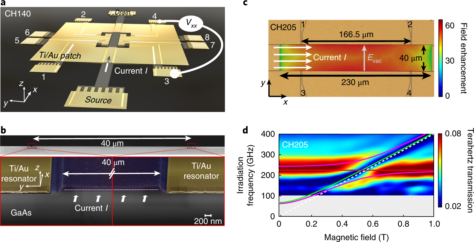
Figure 1: a) Sample schematic. An a.c. current (I = 100 nA) is applied in the x direction along a 40-μm-wide GaAs/AlGaAs Hall bar between the source and drain contacts. CH140 sketched here shows voltage probes located entirely inside the region where the vacuum field created by the LC-like resonator (patterned patch of gold around the Hall bar) has its maximum. b) scanning electron micrograph of a y–z cross-section across the Hall bar channel. c) detailed micrograph of a hall bar with the simulated λ/2-like mode distribution at 205GHz overlaid as a colour map. d) Free-space terahertz transmission through a sample featuring an array of Hall bars coupled to the 205GHz resonator. Magneto-plasmon-polariton dispersion fits are overlaid as magenta curves. They result from the anti-crossing of the magneto-plasmon dispersion (green) and the resonator frequency (red). The computed cyclotron dispersion is shown in white. We observe a normalized light–matter coupling ratio of 20% for the resonator in shown in c).
We then performed magneto-transport measurements. A low frequency AC current is applied from source to drain and the longitudinal and transverse resistances are measured. The geometry of the sample allows to measure many Hall bars from the same chip at the same time in order to have a reliable comparison.
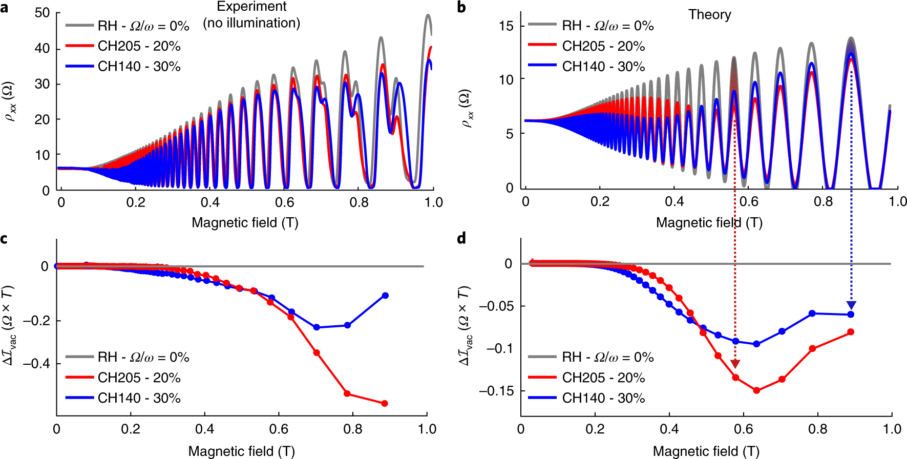
Figure 2: a) The longitudinal resistance for the three Hall bars shows a reduced SdH modulation amplitude in the presence of light–matter coupling. A second series of oscillations appearing above B = 0.6T is due to the spin-split Landau levels and not taken into account in the theory in b. b) Theoretically computed resistance for 0% (grey), 20% (red) and 30% (blue) normalized light–matter coupling corresponding to the three measurements in a. The traces correctly predict depressed oscillation maxima in a wide magnetic field range, while the oscillation phase and minima remain almost unchanged. c),d) Vacuum-field-induced resistivity change integrated over each SdH period for the two cavities for the experimental/theory traces. The red and blue shaded regions, graphically show that \(\small{\Delta I_{vac}}\) represents the vacuum-field-induced change of the area under a peak. For the higher-coupling and lower-resonance-frequency Hall bar CH140, the reduction appears already at lower fields and over a larger magnetic field range. The theory's prediction of \(\small{\Delta I_{vac}}\) for the two cavities shows a good qualitative agreement with the experimental curves in c.
The measurements (Fig. 2) are performed in a dilution refrigerator at an electronic temperature of 100mK without intentional illumination. We observe the well-known Shubnikov–de Haas (SdH) oscillations, arising from the Landau levels crossing the Fermi energy. As visible from Fig. 2a, the upper envelope of the SdH oscillations is modified by the presence of the cavities: a clear reduction of the maxima is observed in a wide range around the resonant magnetic field and depending on the coupling \( \frac{\Omega}{\omega} \) to the cavities’ vacuum field.
A theory based on a linear response theory of a polaritonic system probed by transport, without external illumination, shows a qualitative agreement with the measurements.
One way to confirm these findings is to pump the system with a finite number of excitations. In order to do that, we weakly illuminate the sample by means of a widely tunable single frequency sub-THz source (50-500GHz) and we measure the change in the longitudinal magnetoresistance.
In Fig.3, we show the differential magnetoresistance normalized to input power as a function of magnetic field and irradiation frequency. There is a big difference with respect to the optical measurements (Fig.1d), since now a strong filling factor dependence is noticeable. While measuring transport under irradiation we add an additional selection rule: we probe only the electrons within a narrow energy slice of \( k_bT\) (around 10µeV) around the Fermi energy.
We can therefore distinguish the response of the electrons according to the filling factor of the Landau levels.

Figure 3: The colour map shows the irradiation-induced change in the longitudinal resistance of the Hall bar coupled to the 205GHz resonator normalized to irradiation power \(\small{R(B, \omega_{irr})}\) as a function of irradiation frequency and magnetic field. The black trace above shows the dark (no terahertz irradiation) trace of \( \rho_{xx} \). In contrast to terahertz transmission, the resistance change depends strongly on the value of the resistance \( \rho_{xx} \), and thus on the filling factor ν marked with black arrows.
At half integer filling factors, where the electrons are in the delocalized states, the magnetoresistance is reduced. This reduction shows a dependence on the irradiation frequency, which resembles the expected dispersion for the magneto plasmon polaritons. The effect is similar to what we observed in the dark traces, but enhanced by the external irradiation.
At integer filling factors, so at the localized states, we observe a different dispersion, showing that these states are not contributing to the polariton coupling.
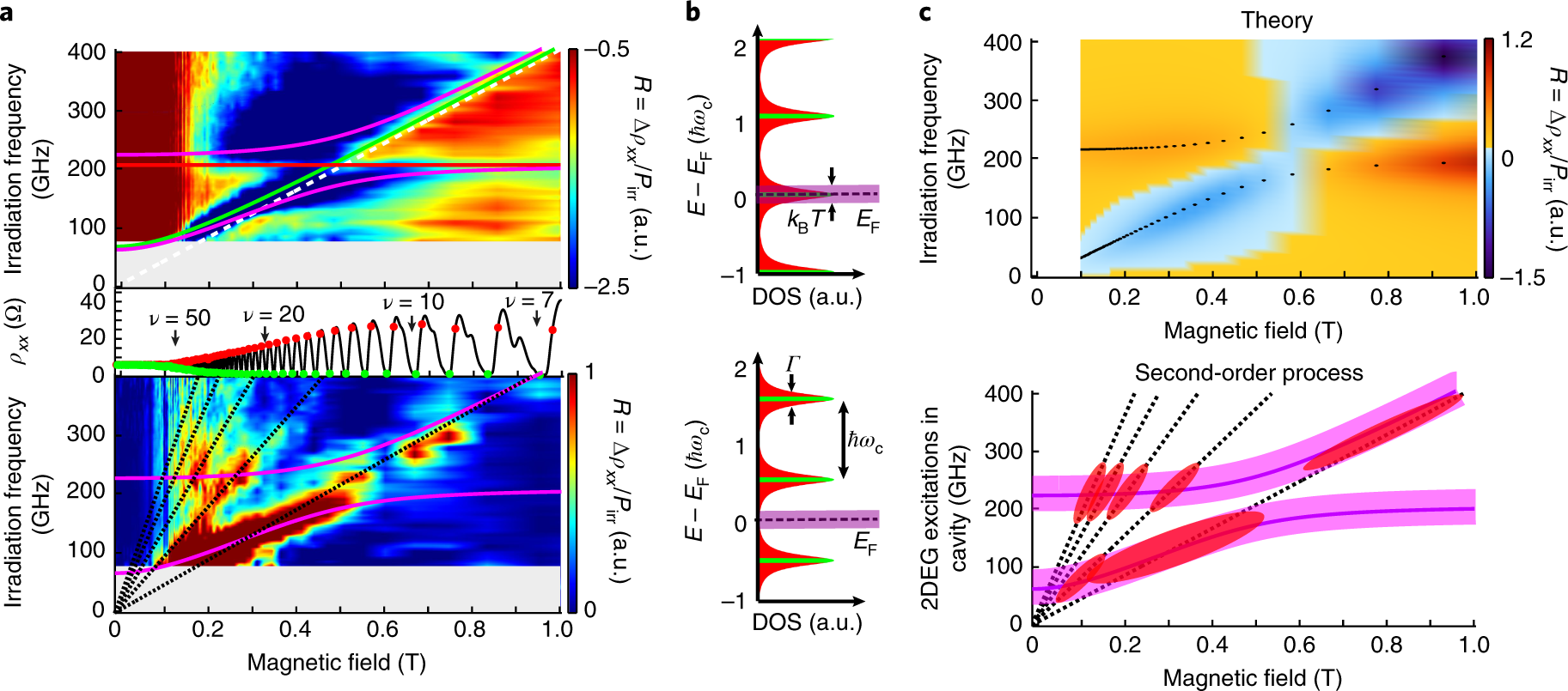
Figure 4: the centre panel shows the longitudinal resistance in the dark (black trace) with the filling factor marked with arrows. For the top and bottom panels, we select only measurements from Fig. 3 taken at approximately half-integer and integer filling factors, where ρxx reaches maxima (red dots on black trace) and minima (green dots) respectively. Top: the longitudinal photo-response \( \small{R = \frac{\Delta\rho_{xx}}{P_{irr}}} \) shows a change when resonant to the magneto-plasmon-polariton dispersions fitted with magenta curves. Polaritons result from the anti-crossing of the resonator frequency (red) and the magneto-plasmon dispersion (green), which itself converges to the cyclotron dispersion (white dashed). When resonant to the polaritons, we have −3 Ω ≲ \( \Delta\rho_{xx} \) ≲ −1 Ω. Bottom: at integer filling factors with localized states at the Fermi energy, a set of linear dispersions appears (black dashed). These are attributed to the inter-Landau level transition (\( \Delta\rho_{xx} \)~ 1 Ω) and its higher orders (\( \Delta\rho_{xx} \)~ 0.3 Ω). Landau levels are represented as Lorentzians with width \(\small{\Gamma = \frac{\hbar}{\tau q}} \) for the case when EF is inside one level (top panel) and exactly in between (bottom). Electrons are delocalized near the centre of each level (green area). The electrons relevant to transport are distributed within a narrow range of width \(\small{k_bT}\)around EF (magenta region).
References
[1] G. L. Paravicini-Bagliani, F. Appugliese, E. Richter, F. Valmorra, J. Keller, M. Beck, N. Bartolo, C. Rössler, T. Ihn, K. Ensslin, C. Ciuti, G. Scalari & J. Faist, Nat. Phys. 15, 186-190 (2019) - external page DOI
[2] G. Scalari, C. Maissen, D. Turčinková, D. Hagenmüller, S. De Liberato, C. Ciuti, C. Reichl, D. Schuh, W. Wegscheider, M. Beck, J. Faist, Science 335, 6074, 1323-1326 (2012) - external page DOI
[3] N. Bartolo and C. Ciuti Phys. Rev. B 98, 205301 (2018) - external page DOI