By RF Tuning
For the application of QCL frequency combs in spectroscopy and sensing, tunability of the light-source spectrum is of great interest. A frequency comb is not only defined by the overall spectral power distribution, which is usually described using the center frequency and the spectral bandwidth, but also the exact spectral position its modes, which is given by the relation for mode n: \(f_n = n \cdot f_{rep} + f_{ceo}\), where \(f_{rep}\) is the intermode spacing and \(f_{ceo}\) is their offset from a comb where \(f_0 = 0\)1. In most standard QCLs2, the tuning parameters are the driving current (DC) and operational temperature, which results in an overall limited tuning range.
In QCL frequency combs, the intermode beating leads to a modulation of the carrier density within the laser cavity, which in turn generates current modulation of the driving current. The corresponding frequencies typically lie within the RF-region of the spectrum and thus, the modulation can be read out using a bias-tee to probe the intermode spacing \(f_{rep}\) using a spectrum analyzer. Using an RF-generator, external modulation can be used to lock the mode-spacing via injection-locking, when close to the free-running value of \(f_{rep}\). This has been shown to lead to improved stabilization of the QCL frequency comb3,4.
In our research, we use strong RF-modulation to not only lock the mode-spacing of the QCL spectrum but also to change the power distribution of the modes. To achieve this, we have developed a laser design where we have minimized RF-losses up to frequencies close to 20 GHz, which is well above the typical mode-spacing around 11 GHz5. The design is shown in Figure 1. Here, the laser ridge has been narrowed for a higher concentration of the RF-field around the active region, with a highly doped substrate and thick gold contacts for a microstrip-like geometry. A dedicated RF-probe with coplanar geometry is used for contacting these devices to avoid losses introduced by wire-bonds.

The comparison between a standard QCL and one with the new design reveals much lower losses and as a result much higher locking ranges, as shown in Figure 2. This means that the new QCLs respond much more strongly to RF-modulation.

High-power RF-injection in these devices leads to a spectral response with a strong frequency-dependence8, which is displayed in the spectral map in Figure 3. There is a clear broadening of the spectrum close to the free-running \(f_{rep}\), which leads to a doubling of the spectral bandwidth compared to the free-running case. Repeating the experiment for different injection powers reveals an upper bound of the maximal bandwidth, which is independent of underlying DC bias throughout the dynamical range of the device.

The high speed of the spectral response to the RF-injection also enables fast switching between separate regions of the spectrum8. One example is shown in Figure 4. This can be used in spectrometer-free sensing applications of substances with broad spectral features.

As shown in Figure 5, in the time domain, the high-power modulation leads to an amplitude modulation and at even higher powers to on-off switching of the device output, i.e. long pulses8.

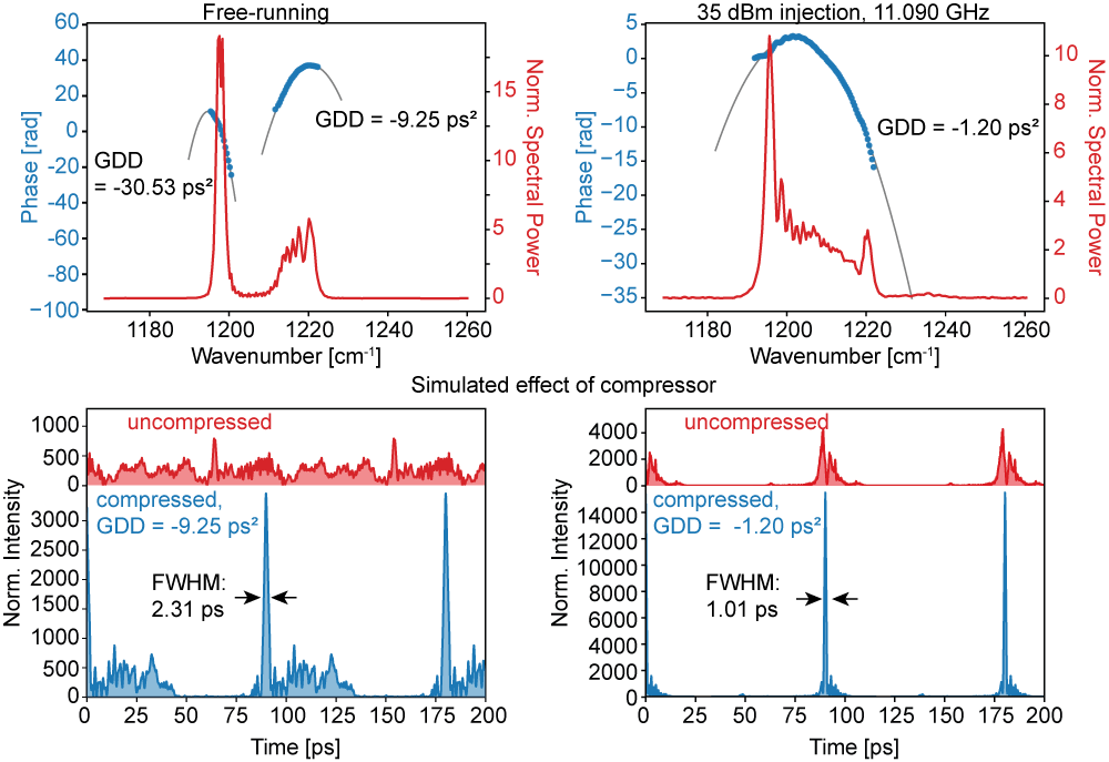
For the generation of shorter pulses with an external compressor6,7, the modification of the output state can be used to optimize the output for a linear chirp8, shown in Figure 6. This has recently been used by our group to generate ultrashort pulses from QCLs.
Our research article about this RF enhanced comb properties can be found external pagehere.
References:
[1] T. Udem, R. Holzwarth, and T. W. Hänsch, “Optical frequency metrology,” Nature, vol. 416, pp. 233–237, 3 2002.
[2] J. Faist, F. Capasso, D. L. Sivco, C. Sirtori, A. L. Hutchinson, and A. Y. Cho, “Quantum Cascade Laser,” Science, vol. 264, pp. 553–556, 4 1994.
[3] J. Hillbrand, A. M. Andrews, H. Detz, G. Strasser, and B. Schwarz, “Coherent injection locking of quantum cascade laser frequency combs,” Nature Photonics, vol. 13, pp. 101–104, 2 2019.
[4] A. Forrer, L. Bosco, M. Beck, J. Faist, and G. Scalari, “RF Injection of THz QCL Combs at 80 K Emitting over 700 GHz Spectral Bandwidth,” Photonics, vol. 7, p. 9, 1 2020.
[5] F. Kapsalidis, B. Schneider, M. Singleton, M. Bertrand, E. Gini, M. Beck, and J. Faist, “Mid-infrared quantum cascade laser frequency combs with a microstrip-like line waveguide geometry,” Applied Physics Letters, vol. 118, p. 071101, 2 2021.
[6] M. Singleton, M. Beck, and J. Faist, “Pulses from a mid-infrared quantum cascade laser frequency comb using an external compressor,” Journal of the Optical Society of America B, vol. 36, p. 1676, 6 2019.
[7] P. Täschler, M. Bertrand, B. Schneider, M. Singleton, P. Jouy, F. Kapsalidis, M. Beck, and J. Faist, “Femtosecond pulses from a mid-infrared quantum cascade laser,” Nature Photonics 2021 15:12, vol. 15, pp. 921–926, 11 2021.
[8] B. Schneider, F. Kapsalidis, M. Bertrand, M. Singleton, J. Hillbrand, M. Beck, and J. Faist, “Controlling Quantum Cascade Laser Optical Frequency Combs through Microwave Injection,” Laser & Photonics Reviews vol. 15, p. 2100242, 12 2021.